 In 1974 satellite weather SMS 1 (Synchronous Meteorological Satellite) satellite was launched as a functioning GeoSyncronous send some pictures to a television station. After several experimental satellite in 1975, it changed into geostasioner orbit.
Monday, September 15, 2008
GeoSyncronous orbit (GSO)
GeoSyncronous orbit is an orbit objects (usually artificial satellite) with the earth as the center, which has the same Period with the rotation of the earth that day or hour 23.9344. The orbital geometry has half the main axis (semi-major axis) length of 42164.17 km. GeoSyncronous with the orbital satellite will be located above a point on the earth at certain hours. Apart from the time the satellite will appear to shift relative to that point. If the satellite GeoSyncronous have the perfect circle of orbit and orbital equator line with the views of the earth, the satellite will appear to be silent, so-called the orbital Geostationer.
 In 1974 satellite weather SMS 1 (Synchronous Meteorological Satellite) satellite was launched as a functioning GeoSyncronous send some pictures to a television station. After several experimental satellite in 1975, it changed into geostasioner orbit.
In 1974 satellite weather SMS 1 (Synchronous Meteorological Satellite) satellite was launched as a functioning GeoSyncronous send some pictures to a television station. After several experimental satellite in 1975, it changed into geostasioner orbit.

Friday, September 12, 2008
Medium Earth Orbit (MEO)
Telecommunication services and the demands of the mobile cellular systems and wireless. From here appear discourse satellite Medium Earth orbit (MEO) and LEO [Low Earth Orbit]. Unlike satellite Geo, which sit on the distance of 22,300 miles above the Earth, LEO satellites gather in the distance about 400 miles only, and the MEO orbit 10,000 km distance between the 36.000 Km. Distance lower, need more advanced technology, allows people to communicate across the world with a mobile phone pocket size. Because of LEO and MEO satellites close together, a network coverage is needed to create the equivalent satellite Geo.
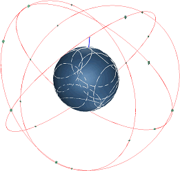 Through the network of satellites that orbit the track orbital, this system is possible to deliver sound quality with a better effect without resonance. but also how, satellite Geo is still better and more suitable for transmission that has a wide spectrum such as television.
 Through the network of satellites that orbit the track orbital, this system is possible to deliver sound quality with a better effect without resonance. but also how, satellite Geo is still better and more suitable for transmission that has a wide spectrum such as television.
Tuesday, September 9, 2008
Low Earth orbit-LEO
Low orbit is an orbit around the Earth between the atmosphere and the Van Allen radiation belt, with a low inclination angle. These limits are not defined exactly, but usually under 1,500 km above the surface of Earth. This orbit is usually located under the intermediate circular orbit (ICO) and far below the geostationary orbit. Orbital lower from here is not stable and will fall quickly because of the atmosphere of friction. A higher orbit from the orbital This is the subject of electronic failure early because of strong radiation and collecting cargo. Orbital inclination angle with a higher usually called a polar orbit. Objects in low Earth orbit to meet
 the gas atmosphere in the thermosphere (about 80-500 km above) or exosphere (approximately 500 km above), depending on the altitude orbit. Most of the flight space probe has been in LEO, including all the various space shuttle and space station mission; one exception is the suborbital test flights as early Mercury Project and the SpaceShipOne flight (which did not achieve the intended LEO), and Project Apollo missions to the Moon (which passes LEO ).
 the gas atmosphere in the thermosphere (about 80-500 km above) or exosphere (approximately 500 km above), depending on the altitude orbit. Most of the flight space probe has been in LEO, including all the various space shuttle and space station mission; one exception is the suborbital test flights as early Mercury Project and the SpaceShipOne flight (which did not achieve the intended LEO), and Project Apollo missions to the Moon (which passes LEO ).
Wednesday, August 20, 2008
Communications Satellites
The basic concept of communications satellites:
o Earth Station
Earth station is the radio communications station that is located on the ground and functions to communication with the space station.
oSatellite Communication
The communication between the satellite earth station through space or through artificial earth satellite passive.
oSatellite Links
It is a point of communication between earth station via a satellite link, and consists of the earth to the satellite (up-link) and a link from the satellite to the earth (down link). Station earth connected to the central switching from the communications network connecting via the link terresterial.
o Earth Station
Earth station is the radio communications station that is located on the ground and functions to communication with the space station.
oSatellite Communication
The communication between the satellite earth station through space or through artificial earth satellite passive.
oSatellite Links
It is a point of communication between earth station via a satellite link, and consists of the earth to the satellite (up-link) and a link from the satellite to the earth (down link). Station earth connected to the central switching from the communications network connecting via the link terresterial.
Saturday, August 9, 2008
Modulation Powerline Communication
PLC (Powerline communication) must work with the signal power / low frequency. Because of high frequency radiation can occur from power cable that can disrupt the frequency of others. This is contrary to the provisions of the SNR because of a variety of high interference can occur. The process of achieving a good SNR value of the constraints faced by the emergence of radiation effects power cable. But the problem can be solved with the methods of modulation:
1. Modulation CDM (Code division multiplexing) or spreads spectrum
Signal information can be scattered in a wide frequency range. The level of the signal information is made with very low expectations will not be subject to the noise level is very high in the PLC.
2. Modulation OFDM (Orthogonal Frequency division multiplexing)
Modulation method is quite stable. Modulastion efficiency can reach 5 bits per Hz higher modulation from the other.
1. Modulation CDM (Code division multiplexing) or spreads spectrum
Signal information can be scattered in a wide frequency range. The level of the signal information is made with very low expectations will not be subject to the noise level is very high in the PLC.
2. Modulation OFDM (Orthogonal Frequency division multiplexing)
Modulation method is quite stable. Modulastion efficiency can reach 5 bits per Hz higher modulation from the other.
Friday, July 25, 2008
PLC (Powerline communication) Applications
The connection to the Internet as a means to distribute data or voice (VoIP) by using the electricity network.
1.High speed digital Internet
Can be reached and to include all the world, quickly and securely through the Internet connection, e-commerce, e-mail, and e-banking.
2. telephony
The phone connection is very strong using the Internet, which provides security and quality of the conversation clear. We can also send and receive messages from the fax machine.
3.Smart Homes
And the use of the remote control in the home via the Internet allows household appliances such as refrigerators, heating systems and other.
4. Security
A system of security in both visual and motion detector can be monitored or to allow the owner or the safety and security.
5.Health Care Service
The monitoring of every person who needs the help of health PLC through an internet connection.
1.High speed digital Internet
Can be reached and to include all the world, quickly and securely through the Internet connection, e-commerce, e-mail, and e-banking.
2. telephony
The phone connection is very strong using the Internet, which provides security and quality of the conversation clear. We can also send and receive messages from the fax machine.
3.Smart Homes
And the use of the remote control in the home via the Internet allows household appliances such as refrigerators, heating systems and other.
4. Security
A system of security in both visual and motion detector can be monitored or to allow the owner or the safety and security.
5.Health Care Service
The monitoring of every person who needs the help of health PLC through an internet connection.
Wednesday, July 9, 2008
Global Positioning System (GPS)
 GPS is the Global Positioning System navigation equipment that is used to determine the position at any time and anywhere by using satellites. Function of the GPS satellites which are always / continuously send or emit code information used to know / identify the location on the earth.
Segments of the GPS:
space segment, user segment, and control segment.
Space segment
Consists of 24 satellites (21 active and 3 as a backup), each of which is the orbit distance with 11,000 miles above the surface of the earth.
User segment
Consists of tools recipient GPS signals from satellites.
Control segment of the earth from the station that serves as a checker to ensure that the GPS satellites to work properly. Examples in everyday life, used to know the search for the presence / position of someone, help in finding the existence of a car on the highway, to know the position of the aircraft, to know the speed of an object, and so forth.
Wednesday, June 25, 2008
Multiple Access of INTELSAT Satellite
 Satellite INTELSAT access using the 2 methods, namely TDMA and FDMA. Time Division Multiple Access with Direct Digital Interface (TDMA / DDI), Digital Speech Interpolation (TDMA / DSI) and Digital Speech Interpolation without.
TDMA is the method used to overcome the back-off and also more flexible in sharing between the satellite to the station and channel. With TDMA, the station can be full access to the satellite transponder with a time slot, so there is no intermodulation strengthening can be maximum, and although troughput high number of multiple access.
Method Frequency Division Multiple Access (FDMA) can be used for analog modulation (FM) or digital modulation (PSK). Location frequency used satellite Internet is the C-band and Ku-Band.
Saturday, June 7, 2008
INTELSAT Satellite
 INTELSAT Satellite was first launched on 28 June 1965, which was placed in geostationary orbit over the Atlantic ocean. Lunch and operated as the orbit Early Phase (LEOP) headquartered in Washington DC. To access the INTELSAT satellite, INTELSAT has the characteristics that vary for each earth station with the station type:
Standard A has a nominal G / T 35.0 dB / K and the operating frequency band at 6 / 4 GHz for international service.
Standard B has a nominal G / T 31.7 dB / K and the operating frequency band at 6 / 4 GHz for international service.
Standard C has a nominal G / T 37.0 dB / K and frequency bands operating in the 14/11 or 14/12 GHz GHz for international service.
Standard E, the Standard E-1 has a nominal G / T 25.0 dB / K, Standard E-2 has a nominal G / T 29.0 dB / K, Standard E-3 has a nominal G / T 34.0 dB / K and the operating frequency band at 14 / 11 GHz or 14/12 GHz for services to Intelsat Business Services (IBS), Intermediate Data Rates (IDR) international, Internet Trunking Service (ITS) and VSAT. using Turbo coding with QPSK / OQPSK (Standard E-1).
Standard F, Standard M-1 has a nominal G / T 22.7 dB / K, Standard F-2 has a nominal G / T 27.0 dB / K, Standard M-3 has a nominal G / T 29.0 dB / K and the operating frequency in the band 6 / 4 GHz for services to Intelsat Business Services (IBS), Intermediate Data Rates (IDR) international, Internet Trunking Service (ITS) and Turbo coding using VSAT with QPSK / OQPSK (Standard F-1).
Standard G, does not have a specific G / T segment for satellite Internet access services to domestic and international. This standard allows the use of the G modulation techniques and access to other, that is not in the Standard A and M and only the general characteristics of the RF limits.
Standard H, Standard H-2 has a nominal G / T 15.1 dB / K, Standard H-3 has a nominal G / T 18.3 dB / K, Standard H-4 has a nominal G / T 22.1 dB / K and the operating frequency in the band 6 / 4 GHz for services to Intelsat Business Services (IBS), Intelsat DAMA, the Internet Trunking Service (ITS) and Turbo coding using VSAT with QPSK / OQPSK.
Standard K, K-2 Standard has a nominal G / T 19.8 dB / K, K-3 standards have nominal G / T 23.3 dB / K, and in the operating frequency band, 14/11 or 14/12 GHz for services to Intelsat Business Services (IBS), the Internet Trunking Service (ITS) and Turbo coding using VSAT with QPSK / OQPSK.
Monday, May 26, 2008
Increasing Capacity In The System Cellular
There are several ways to increase the capacity of the system cellular.
Using Frequency reuse
Dense population of cells to be overloaded with the relocation frequency of cells that are not overloaded.
Conducting Cell-Splitting
Cells with dense population is doing cell splitting into several new cells into a new cluster of small to add more capacity. This is done by making changes in the parameters of the transmission link budget recalculate and also make a new design for the antenna height of the BTS.
Two types of cell splitting:
• Permanent Splitting: Cell of the permanent, it must be done to the planning cooked to the following matters:
1. The number of channel
2. Power transmitter
3. The frequency allocated
4. Determination of Cell Site
5. Traffic load
• Dynamic Splitting: This technique is also referred to as the "Real-time splitting" because cell division is done only at the time it needed to overcome the traffic density that is temporary

Conducting Sectoring
Dividing cells become sectors, usually 3 sectors (each 120 °) or 6 sectors (each 60 °). Each sector will be served by a directional antenna and the frequency varies. Interesting directional antenna to reduce co-channel, which makes a smaller cluster with a larger capacity.
Using Frequency reuse
Dense population of cells to be overloaded with the relocation frequency of cells that are not overloaded.
Conducting Cell-Splitting
Cells with dense population is doing cell splitting into several new cells into a new cluster of small to add more capacity. This is done by making changes in the parameters of the transmission link budget recalculate and also make a new design for the antenna height of the BTS.
Two types of cell splitting:
• Permanent Splitting: Cell of the permanent, it must be done to the planning cooked to the following matters:
1. The number of channel
2. Power transmitter
3. The frequency allocated
4. Determination of Cell Site
5. Traffic load
• Dynamic Splitting: This technique is also referred to as the "Real-time splitting" because cell division is done only at the time it needed to overcome the traffic density that is temporary

Conducting Sectoring
Dividing cells become sectors, usually 3 sectors (each 120 °) or 6 sectors (each 60 °). Each sector will be served by a directional antenna and the frequency varies. Interesting directional antenna to reduce co-channel, which makes a smaller cluster with a larger capacity.
Tuesday, April 15, 2008
Interference On Radio Waves
Communications that occur in the sellular using radio waves. Radio communication utilizing electromagnetic waves in the transmission of data on the air interface. The data is passed over the interface is not always accepted in the Receiver intact, but the data will have a disability.
Likewise for the transmission of the signal (the conversation) in the water interface will have several obstacles that lead to sound/voice can not be accepted by both.
Constraints in the transmission of signals that there may be caused by:
Pathloss
Decrease the signal strength that occurs depending on the distance between the transmitter and Receiver. So that MS is beyond the reach of the BTS.
Time Alligment
Time used for the transmission of MS signals that are influenced by distance from the BTS to MS.
Rayleigh Fading
Interference signal reception / signal caused by the weak signals received are some signals that the reflection from the nearest object and not a signal that is received directly.
Time Dispersion
Transmission constraints that occur when the digital signal to reach the same Receiver in a different time because there is a rebound occurs that causes a signal not synchronized.
Likewise for the transmission of the signal (the conversation) in the water interface will have several obstacles that lead to sound/voice can not be accepted by both.
Constraints in the transmission of signals that there may be caused by:
Pathloss
Decrease the signal strength that occurs depending on the distance between the transmitter and Receiver. So that MS is beyond the reach of the BTS.
Time Alligment
Time used for the transmission of MS signals that are influenced by distance from the BTS to MS.
Rayleigh Fading
Interference signal reception / signal caused by the weak signals received are some signals that the reflection from the nearest object and not a signal that is received directly.
Time Dispersion
Transmission constraints that occur when the digital signal to reach the same Receiver in a different time because there is a rebound occurs that causes a signal not synchronized.
Sunday, April 6, 2008
The Beautiful Fountain
This is a very beautiful place, where we can see the water fountain unique. That all people can see the image directly but through this we can see, although not directly to the place. I may never be able to go to a beautiful place, as far away and required a lot of money to go. Also, some people may have to go to that place for a vacation to enjoy the scenery beautiful fountain.
 This fountain is located in Tivoli
 This fountain is located in Barcelona
 This fountain is located in Tivoli
Maybe one day I will go see a fountain that is beautiful.
 This fountain is located in Tivoli
 This fountain is located in Barcelona
 This fountain is located in Tivoli
Maybe one day I will go see a fountain that is beautiful.
Sunday, March 16, 2008
Wireless Application Protocol
Wireless Application Protocol (WAP) is international open standard for applications that use wireless communication. The main objective to build applications that can access the Internet from the phone handheld or Personal Digital Asistant (PDAs). With the WAP users can use cellular to access the Internet and obtain facilities from each mobile phone.
Opening page site, to view information such as the exchange of information or news, weather, e-mail, even to conduct financial transactions. There are several versions of WAP, among others, WAP 2.0 and 1.2.1. WAP 1.2.1 can only be page displays only simple compared with the WAP 2.0 support language XHTML (extensible hypertext markup language) and image.
WAP in a the first time as a communications protocol that move does not depend on the system certain. WAP is designed as part of the system in the future as well as Bluetooth and GPRS. WAP is a communications protocol that consists of moving several layers and can be run on a different network system.

WAP working with almost the same way the Internet works now. Required WAP gateway to bridge the mobile phone with Internet data and send in receive data. This is the same case with PC users (Personal Computer) that require ISPs (Internet Service Provider) as the gateway to bridge the PC with the Internet. Besides, mobile phone, which is also used to be WAP-enabled, namely is equipped with WAP technology that can be used to access the Internet, mobile phones and card-or SIM cards (Subscriber Identity Module) from operator of cellular telecommunications facilities that provide services to General Packet Radio Services (GPRS)
Opening page site, to view information such as the exchange of information or news, weather, e-mail, even to conduct financial transactions. There are several versions of WAP, among others, WAP 2.0 and 1.2.1. WAP 1.2.1 can only be page displays only simple compared with the WAP 2.0 support language XHTML (extensible hypertext markup language) and image.
WAP in a the first time as a communications protocol that move does not depend on the system certain. WAP is designed as part of the system in the future as well as Bluetooth and GPRS. WAP is a communications protocol that consists of moving several layers and can be run on a different network system.

WAP working with almost the same way the Internet works now. Required WAP gateway to bridge the mobile phone with Internet data and send in receive data. This is the same case with PC users (Personal Computer) that require ISPs (Internet Service Provider) as the gateway to bridge the PC with the Internet. Besides, mobile phone, which is also used to be WAP-enabled, namely is equipped with WAP technology that can be used to access the Internet, mobile phones and card-or SIM cards (Subscriber Identity Module) from operator of cellular telecommunications facilities that provide services to General Packet Radio Services (GPRS)
Saturday, March 8, 2008
Parameters Antenna
 Parameters of the antenna used to describe a performance antenna. Parameters of the antenna can be related to each other when someone wants to design an antenna, although not all parameters must be considered in depth. Type of antenna parameters include:
1. Radiation Pattern
Radiation pattern is a graphical representation of electricity and magnetic field in the space coordinates. In many cases, the pattern radiation specified in the region and far-field is represented as a function of directional coordinates.
Radiation types:
• Isotropic
Antenna radiation pattern ideal lossless or radiation that direction is the same to all (shaped like a ball). Radiation patterns such as this are usually used as a reference antenna with the unit of measurement dBi.
• Directional
Radiation pattern that is better for a particular direction (for unidirectional and bidirectional one direction to two directions).
• Omnidirectional
The directional radiation pattern, but all the same to the direction (the vertical axis there is no antenna radiation). Radiation pattern is shaped like a sinker. Radiation pattern like this used to broadcast communications.
2. Radiation intensity
Parameters comparison shows that the antenna power by the radiation emanating from an antenna per unit solid angle.
3. Directional
Parameters that indicate the value gain directive on the maximum. In a certain direction, the gain directivity comparison radiation intensity in the direction compared with the intensity radiation antenna references.
4. Gain
Parameters which indicate the ratio of power on the antenna of the antenna with a power reference. Relations between the directivity and gain can be written as follows: G = μD, where the G (Gain), D (Directivity) and μ (the ratio of the intensity of radiation).
5. Antenna efficiency
Consider the efficiency of the antenna total loss that occurs in the input terminals and an antenna inside the structure loss like this can happen because:
• reflection result does not match the transmission channel and antenna.
• Loss conduction and dielectric.
6. Half Power Beam Width (HPBW)
HPBW is the angle between two directions of radiation from half the intensity of the beam maximum value. If converted in dB, the value of HPBW obtained when the power down 3dB.
7. Efficiency beam
This parameter is often used to determine the quality of transmitting and receiving antenna. Efficiency is the ratio of beam power that emanated (received) in the cone angle compared with the power that emanated (accepted) by the antenna.
8. Bandwidth
Bandwidth is the frequency range on both sides of the center frequency (resonance frequency of the dipole antenna), which characteristics of the antenna (impedance input, the radiation pattern, beam width, polarization, the side lobe level, gain, beam direction, the efficiency of radiation) is in the optimal value. Narrow band to this antenna. Meanwhile, for Broadband, the bandwidth is a comparison between the frequency up and down in frequency levels that can be accepted.
9. Polarization
Parameters which indicate that the wave dielectric radiation when the antenna work. When the direction of polarization is not mentioned, polarization in direction is considered the maximum gain. Kind of polarization:
• linear polarization
A wave of Harmonic linear polarization at a point if the electric field (magnetic fields) in the direction of the move in a straight direction all the time.
• circular polarization
A wave of harmonic polarization circle on a point if the electric field (magnetic fields) in the direction of the move in the direction of the coil as a function of time.
• ellipse polarization
A wave of harmonic polarization linear at a point if the electric field (magnetic fields) in the direction of the move formed Locus ellipse in the space coordinates.
10. Impedance Input
This parameter shows the ratio of voltage to the antenna terminal on the flow rate or electric field component of the magnetic fields on a point or value impedance existing antenna on it.
Wednesday, March 5, 2008
The Definition Antenna
 Antenna is a metal device (in the form of a bar or wire) that functions to send and receive radio waves. Antenna is the tool to emit radiation or receive radio waves [IEEE Standard Definition]. Based on two standard definition above, an antenna is a conductor or a conductor group, which is responsible for radiating energy electromagnetic radiation into the air and free to collect (receive) electromagnetic energy from another free air.
Antenna change electrical energy from a transmitter into the system of energy and emit electromagnetic radiation into the air. Conversely, an antenna gathered energy electricity will be distributed to the recipient's system. Free air known as the air interface.
How does the antenna?
Radiation is a disturbance that occurred in the electromagnetic field which propagates out from the source of interference. Interference itself derived from sources that flow changed in that time has accelerated the flow of distribution. An electric current or static electric current that moves with constant speed in the straight channel transmission can not emit radiation.
However, a flow that moves with constant speed can be experienced on the radiation conditions below:
• meet the end of the channel transmission.
• find a channel transmission, which trap.
• transmission lines have shaped curve.
• transmission lines to meet the discontinue.
Meanwhile, a flow that can emit radiation accelerated despite creeping through the transmission lines straight.
Subscribe to:
Posts (Atom)